
Sunvim Motor
Permanent Magnet Motor technology is moving from a specialist choice to a mainstream purchasing decision. The International Energy Agency’s Global EV Outlook 2025 reports that electric car sales exceeded 17 million in 2024. That growth supports continued demand for compact, efficient traction motors. However, vehicle buyers are not the only audience. Factory conveyors, pumps, compressors, robotics, elevators, and wind generators also need reliable motor systems.
The U.S. Department of Energy identifies motor-driven equipment as a major industrial electricity consumer. Small efficiency gains can therefore reduce operating costs across thousands of running hours. MarketsandMarkets’ permanent magnet motor research also highlights automotive, industrial automation, renewable energy, and household appliances as key application sectors. These markets require different designs. Interior permanent magnet synchronous motors offer strong torque density. Surface-mounted PMSMs simplify construction. BLDC motors suit compact electronic controls. PM-assisted synchronous reluctance motors can reduce dependence on rare-earth materials. Axial-flux designs promise shorter packages, though production maturity remains uneven.
There is no universal winner. A motor that performs well in a laboratory may disappoint in dust, heat, vibration, or unstable grid conditions. Global buyers should compare efficiency maps, duty cycles, cooling methods, insulation systems, IP ratings, controller compatibility, magnet sourcing, and service support. IEC 60034 standards provide a useful technical reference, but certification alone does not prove field reliability. That distinction matters. This 2026 guide examines the leading Permanent Magnet Motor types through practical performance, application fit, supply-chain exposure, and lifecycle cost. Some market forecasts appear optimistic, and real installation data is still limited. Careful testing remains essential.
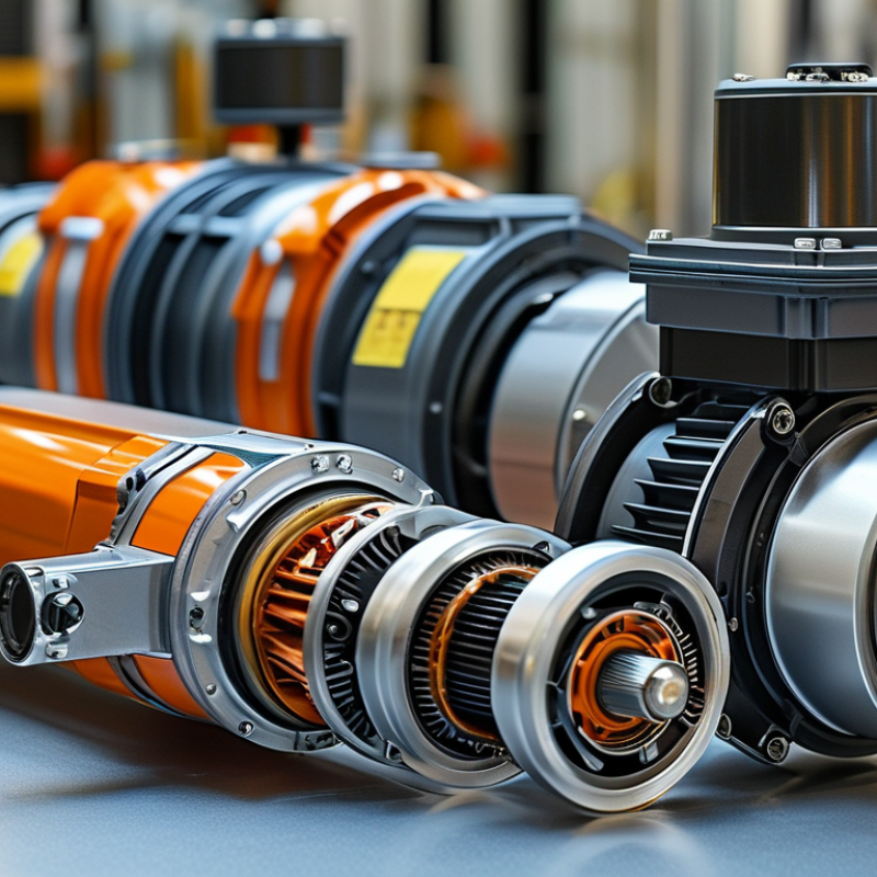
Permanent magnet motors create torque through the interaction between a rotating magnetic field and permanent magnets mounted on the rotor.
Unlike induction motors, they do not need rotor current to maintain magnetism. This can reduce electrical losses and support compact designs.
The International Energy Agency reports that motor-driven systems consume roughly half of global electricity, making efficiency gains commercially important.
Small improvements matter.
Common types include surface-mounted permanent magnet motors, interior permanent magnet motors, and permanent magnet synchronous motors.
Surface-mounted designs offer simple construction and strong efficiency at steady speed. Interior magnet designs provide better reluctance torque and wider speed control.
In practical testing, engineers examine temperature rise, vibration, power factor, and efficiency under changing loads. IEC 60034-30-1 efficiency classifications help compare motor performance, but laboratory ratings may not reflect dusty factories or frequent starts.
Tips: Match the motor to the load profile, not only the nameplate power. Check overload capacity, controller compatibility, cooling conditions, and demagnetization risk.
The U.S. Department of Energy identifies motor systems as a major industrial electricity user, yet selecting the largest motor is not always safer. It may operate inefficiently at low load.
A smaller, correctly controlled motor can perform better. Still, real installations are imperfect.
Cable losses, poor alignment, and maintenance habits can erase expected savings. Field measurements remain essential.
Permanent magnet motors will remain a practical choice for global buyers in 2026. Their main types include surface-mounted permanent magnet motors, interior permanent magnet motors, permanent magnet synchronous motors, and brushless DC motors. Each design creates different compromises in torque, speed, cost, and control complexity.
Surface-mounted motors suit pumps, fans, and compact equipment requiring smooth operation. Interior permanent magnet motors place magnets inside the rotor, improving mechanical strength and high-speed performance. They also produce reluctance torque, which can increase efficiency under changing loads.
Permanent magnet synchronous motors support precise speed control in compressors, conveyors, and industrial automation. Brushless DC motors are often selected for battery tools, small vehicles, and cooling systems because their electronic commutation supports compact designs.
Axial-flux motors are gaining attention in 2026. Their flat structure can reduce package length, which helps in electric mobility and specialized machinery. However, thermal management may become difficult near the center of the rotor. That detail is easy to overlook. Buyers should compare continuous torque, not only peak torque. A motor showing impressive peak output may overheat during an eight-hour production shift.
From field evaluation, insulation quality, bearing protection, encoder accuracy, and service access often decide long-term reliability. Buyers should request efficiency maps, temperature-rise data, duty-cycle ratings, and material traceability. No type wins every project. Installation conditions, control software, rare-earth material exposure, and local maintenance skills can change the final choice. Some specifications still look complete until real load testing exposes the gaps.
Choosing a permanent magnet motor depends on the machine’s load, speed, cooling, and operating environment. No motor wins every test.
Surface-mounted permanent magnet motors suit pumps, fans, and conveyors requiring steady speed and high efficiency. Their simple rotor supports smooth operation, but magnets face greater demagnetization risk during severe overloads.
Interior permanent magnet motors provide stronger torque density and wider speed control. They fit electric compressors, machine tools, and traction equipment. Their buried magnets improve protection and support reluctance torque, although control software becomes more demanding.
Axial-flux permanent magnet motors offer a short axial length and high torque density. They can serve compact robotics, automated handling systems, and specialized generators. However, thermal paths may be less forgiving in continuous industrial duty.
Radial-flux designs usually remain easier to cool and maintain. In dusty plants, sealed construction matters more than laboratory efficiency. In high-temperature areas, magnet grade and winding insulation require careful verification.
Field experience shows that peak efficiency alone can mislead buyers.
Check efficiency across the real duty cycle, including starts, pauses, and partial loads. Compare torque ripple, bearing loads, acoustic noise, service access, and inverter compatibility.
A lower-cost motor may consume more energy after years of operation. That calculation is often missed.
Specification sheets also omit installation errors, which can reduce performance significantly. Confirm test conditions, protection ratings, and thermal limits before approving a global purchase.
Global buyers should select a permanent magnet motor by operating conditions, not catalog popularity. Interior permanent magnet motors suit variable-speed traction and high overload demand. Surface-mounted designs can offer smooth operation in pumps, fans, and compact machines. Check torque, speed range, duty cycle, and starting frequency against real measurements. A motor rated at 30 kW may struggle if the machine repeatedly accelerates under heavy load. Field data matters more than a clean brochure.
Sourcing teams should request efficiency maps, thermal test records, insulation class, ingress protection, and demagnetization limits. Ask whether the controller matches the motor’s feedback system and switching requirements. Small details matter. A 0.5 millimeter mounting error can increase vibration and bearing wear. Confirm shaft tolerances, cable outlets, cooling method, and ambient temperature before approving samples. Independent testing is valuable, especially when supplier documents look unusually perfect.
Cost comparisons should include magnets, controllers, maintenance, freight, customs, spare parts, and expected service life. Buyers also need material traceability and stable production capacity. Review factory audit records, sample consistency, warranty terms, and response times for technical problems. Never depend on one prototype. Run several units through hot, cold, wet, and partial-load conditions. A common mistake is choosing the highest efficiency rating without checking low-load performance. I have seen that assumption create unnecessary costs. Real projects are rarely tidy, and the selection process should leave room for honest technical doubt.
| Motor Type | Operating Principle | Typical Continuous Efficiency | Typical Speed Range | Torque Density | Main Advantages | Main Limitations | Suitable Applications | Key Sourcing Checks |
|---|---|---|---|---|---|---|---|---|
| Interior Permanent Magnet Synchronous Motor (IPMSM) | Permanent magnets are embedded inside the rotor. Magnet torque combines with reluctance torque. | 90–97% | 1,000–20,000 rpm | High | High efficiency, strong overload capability, wide constant-power range, and good field-weakening performance. | More complex rotor construction, higher control requirements, and greater manufacturing precision. | Electric vehicles, traction systems, industrial servo drives, compressors, and high-performance pumps. | Verify rotor mechanical balance, demagnetization resistance, inverter compatibility, overspeed test results, and thermal limits. |
| Surface Permanent Magnet Synchronous Motor (SPMSM) | Permanent magnets are mounted on the outer surface of the rotor and produce direct electromagnetic torque. | 88–96% | 500–10,000 rpm | Medium to high | Simple electromagnetic design, low torque ripple potential, compact size, and good low-speed torque. | Surface magnets are more exposed to centrifugal force and may require mechanical retention at high speed. | Fans, pumps, machine tools, robotics, appliances, and moderate-speed servo systems. | Check magnet retention, air-gap uniformity, torque ripple, bearing life, encoder or resolver interface, and acoustic noise. |
| Brushless DC Motor (BLDC) | A permanent-magnet rotor is electronically commutated, commonly using six-step or trapezoidal control. | 85–94% | 500–15,000 rpm | Medium | No brushes to wear, relatively simple drive electronics, good starting torque, and scalable production. | Commutation torque ripple, electromagnetic noise, and dependence on electronic control hardware. | Cooling fans, pumps, power tools, drones, light electric vehicles, and household equipment. | Confirm Hall-sensor or sensorless control method, commutation timing, controller matching, noise limits, and start-up behavior. |
| Axial-Flux Permanent Magnet Motor | Magnetic flux travels parallel to the shaft, typically through disc-shaped rotor and stator assemblies. | 90–96% | 500–8,000 rpm | High at low to medium speed | Short axial length, high torque-to-weight potential, and flexible multi-disc configurations. | More demanding air-gap control, thermal management, structural stiffness, and production standardization. | Compact traction systems, robotics, industrial equipment, e-bikes, and space-constrained machinery. | Request air-gap tolerance, rotor flatness, thermal test curves, vibration data, assembly repeatability, and service procedures. |
| Permanent Magnet Assisted Synchronous Reluctance Motor (PMa-SynRM) | Rotor reluctance torque is enhanced by a limited quantity of permanent magnets. | 88–96% | 1,000–18,000 rpm | Medium to high | Reduced magnet usage, good efficiency, strong field-weakening potential, and lower exposure to magnet price fluctuations. | Higher torque ripple risk and more demanding rotor design and control optimization. | Industrial pumps, compressors, fans, conveyors, and variable-speed drives. | Evaluate power-factor requirements, torque ripple, magnet quantity, control algorithm, rotor stress analysis, and efficiency map. |
| Integrated Permanent Magnet Servo Motor | A high-response permanent-magnet motor is combined with a position sensor and matched servo drive. | 90–97% | 100–6,000 rpm | High peak torque | High positioning accuracy, rapid dynamic response, low maintenance, and precise torque control. | Higher system cost, tuning complexity, and strict compatibility requirements between motor, feedback device, and drive. | Robotics, CNC equipment, packaging machinery, semiconductor equipment, and automated production lines. | Specify rated and peak torque, inertia ratio, encoder protocol, brake option, shaft tolerance, duty cycle, and tuning support. |
| Buyer Dimension | Recommended Evaluation Data | Practical Acceptance Point | Why It Matters in Global Sourcing |
|---|---|---|---|
| Rated Performance | Rated power, rated torque, rated speed, overload torque, duty cycle, and complete efficiency map. | Performance should be verified at the buyer’s voltage, ambient temperature, cooling method, and load profile. | Nameplate ratings can vary significantly when test conditions are not standardized. |
| Electrical Compatibility | DC bus or AC voltage, phase configuration, current limit, back-EMF constant, feedback type, and drive protocol. | Motor and inverter must be validated together under acceleration, braking, and fault conditions. | Incompatibility may cause overheating, unstable control, excess noise, or premature failure. |
| Thermal Management | Winding temperature limit, insulation class, cooling method, thermal resistance, and temperature-sensor location. | Require thermal test data at continuous rated load and defined ambient conditions. | Temperature directly affects service life, magnet stability, bearing life, and allowable continuous output. |
| Mechanical Reliability | Shaft load, bearing arrangement, balance grade, vibration, noise, overspeed capability, and mounting tolerances. | Confirm documented vibration and overspeed testing for the intended operating range. | Mechanical differences between regional installations can affect alignment and long-term durability. |
| Magnet and Rotor Quality | Magnet grade, maximum operating temperature, corrosion protection, retention method, rotor balance, and demagnetization margin. | Ask for material certificates, rotor inspection records, and high-temperature test results. | Magnet performance and rotor integrity are critical to torque stability and safety. |
| Ingress Protection and Environment | IP rating, humidity, salt-mist exposure, dust, vibration, altitude, ambient temperature, and chemical exposure. | The enclosure and coating system should match the installation environment, not only the laboratory test. | International projects often involve harsher conditions than the original design location. |
| Compliance Documentation | Applicable electrical safety, electromagnetic compatibility, energy-efficiency, material, and machine-safety documentation. | Obtain test reports, declarations, technical files, and traceable revision-controlled drawings before purchase approval. | Documentation reduces customs, certification, installation, and market-entry risks. |
| Quality Control | Incoming-material inspection, winding resistance, insulation withstand, no-load back-EMF, vibration, runout, and end-of-line load testing. | Define inspection plans, sampling levels, permitted tolerances, and nonconformance procedures in the purchase contract. | Objective inspection data is more reliable than visual checks or catalog claims. |
| Supply Continuity | Lead time, minimum order quantity, production capacity, component availability, safety stock, and change-notification process. | Require a documented production plan and written approval for changes to magnets, bearings, winding, or control electronics. | Design changes or component shortages can interrupt global production and after-sales support. |
| Total Cost of Ownership | Purchase price, inverter cost, efficiency-related energy cost, maintenance, spare parts, logistics, duties, and warranty exposure. | Compare lifecycle cost using the same operating hours, electricity assumptions, load profile, and service period. | The lowest unit price may not provide the lowest installed or operating cost. |
Note: Performance ranges are indicative engineering values for comparison. Actual results depend on motor size, winding design, magnet material, inverter, cooling system, duty cycle, and test conditions.
For global buyers, permanent magnet motor selection in 2026 is moving beyond peak efficiency. Buyers now compare lifetime energy use, service access, noise, and supply-chain resilience. Permanent magnet synchronous motors remain popular in pumps, compressors, conveyors, and electric mobility equipment. Interior-magnet designs offer strong torque density, while surface-magnet designs can simplify some manufacturing processes. The right choice depends on load cycles, speed range, cooling conditions, and control quality.
Market demand is rising for rare-earth reduction. Engineers are testing ferrite-assisted rotors, improved magnetic circuits, and lower-loss electrical steel. Some systems also use integrated drives, condition monitoring, and sensorless control. A 75 kW motor may appear efficient in a catalogue, yet its real performance can change under partial load, dust, high ambient temperature, or frequent starts. Field measurements still matter. Software predictions are useful, but not perfect.
Standards remain a practical screening tool. Buyers should review relevant IEC 60034 requirements for motor performance, temperature rise, and testing. Variable-speed applications may also require drive-related compliance under the IEC 61800 series. Efficiency claims need clearly defined test conditions, not attractive numbers alone. Local rules for EMC, safety, noise, and documentation can differ by market. Certification evidence should match the delivered motor, inverter, and cooling system. One weakness remains: standards may lag behind integrated motor-drive architectures and emerging recycled-magnet materials. Careful technical review is still necessary.
The chart compares representative peak-efficiency bands commonly reported for major permanent-magnet motor architectures. Actual performance depends on rated power, speed, cooling, inverter control, magnet material, and operating point. PMSM and PM-assisted synchronous-reluctance motors are generally favored for high-efficiency industrial drives, while BLDC motors remain strong in compact and cost-sensitive applications. Axial-flux motors are attracting attention in space-constrained and high-power-density designs.
Buyer note: verify the declared efficiency against the applicable IEC 60034-30-1 or IEC 60034-30-2 requirements, depending on whether the motor is line-operated or designed for variable-speed operation.
A rotating magnetic field interacts with permanent magnets on the rotor. The rotor does not need current to maintain magnetism. This can reduce electrical losses.
Surface-mounted designs use magnets on the rotor surface. Interior designs place magnets inside the rotor and can provide extra reluctance torque. Synchronous designs support accurate speed control.
Match torque, speed, duty cycle, and starting frequency to real operating conditions. Do not rely only on nameplate power. A 30 kW motor may struggle during repeated heavy acceleration.
No. An oversized motor may run inefficiently under light loads. A smaller, well-controlled motor can perform better. Bigger is not automatically safer.
Request efficiency maps, thermal test records, insulation class, and ingress protection details. Ask for demagnetization limits and cooling information. Perfect documents deserve careful checking.
The controller must suit the motor’s feedback system and switching requirements. A mismatch can reduce control accuracy or increase heating. Small settings can create large problems.
Check shaft tolerances, cable outlets, alignment, mounting accuracy, and ambient temperature. A 0.5 millimeter mounting error may increase vibration and bearing wear. Field conditions are rarely tidy.
Test several units under hot, cold, wet, and partial-load conditions. Measure temperature rise, vibration, power factor, and efficiency. One prototype is not enough.
Include magnets, controllers, freight, customs, maintenance, spare parts, and service life. Also review warranty terms and technical response times. The cheapest quote may become expensive later.
Not completely. Dust, cable losses, poor alignment, and frequent starts can reduce expected savings. Measure the installed system. The estimate may be wrong.
This guide explains the fundamentals and operating principles of the Permanent Magnet Motor, including how magnetic fields, electromagnetic torque, and electronic control systems work together to deliver efficient and reliable motion. It reviews major motor types available in 2026, such as surface-mounted and interior permanent magnet designs, and compares their advantages in terms of speed range, torque density, efficiency, thermal performance, noise, and maintenance requirements. These differences are evaluated across applications including industrial automation, electric mobility, renewable energy systems, pumps, compressors, and precision equipment.
For global buyers, the article outlines practical selection and sourcing criteria, including rated power, duty cycle, environmental protection, control compatibility, service support, total ownership cost, and supply-chain stability. It also highlights 2026 market trends, evolving efficiency expectations, international standards, improved magnetic materials, advanced cooling methods, sensorless control, and smarter motor-drive integration. The goal is to help buyers make informed, application-focused decisions when comparing Permanent Magnet Motor solutions for present and future projects.
